Basic HTML Version


CONTROLS
The DUPLEX-S 1600, 2600 and 3600 ventilator units can
controls and the sellection software. Units do not have to be
be equipped with built-in controls providing complete
equipped with controls – individual components are only
functionality of the unit with its accessories. Thanks to
connected to a terminal block.
integration of the controls into the unit simple commisioning
A special ATREA selection software may be used to generate
of the unit and full functionality is guaranteed. There is no risk
all control type selection including drawings printouts.
with compatability of components during installation.
The controls enable connection to management systems –
more information in the description of the respective
Type
Use
Controller
„Without
controls“
– all components with power supply are connected to a
terminal block outside the unit
–
more components are included upon customer's
request (exact actuator type, sensors, thermostats,
pressure switches etc.)
– good for applications where third party control is
supplied separately – e.g. large buildings with building
management systems
– not applicable
„RD4“ controls
Standard functions of the „RD4“ controls
– EC fan speed control (based on selected mode)
– automatic by-pass damper position (heat and cool
recovery)
– evaluates and prevents emergency limits based on
measured temperature
– ventilation and temperature weekly program setting
– standard built-in Ethernet connection for remote
internet communication
– inputs for switching using 230 V
(4 inputs – 3 delayed, 1 instantenious) – switch e.g.
from bathrooms etc.
– optional connection of CO or RH sensor
2
– max. 2 sensors with a switch or 0 – 10 V output
– outputs for electric preheater and heater control
(pulse 10 V) or hot-water control (0 – 10 V)
Additional RD-IO modules
– optional manometer connection to ensure constant
airflow control (see Constant airflow and pressure
control on previous page)
– constant pressure control
– cooling control outputs (DX- or chilled-water cooling)
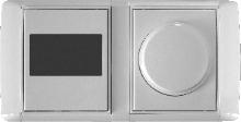
CP 18 RD
installation in the standard
recessed dual box on the wall
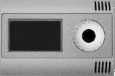
CP 19 RD
installation on wall
„DC“ controls
Standard functions of the „DC“ controls
– EC fan speed control (based on selected mode)
– automatic by-pass damper position (heat and cool
recovery)
– evaluates and prevents emergency limits based on
measured temperature
– ventilation weekly program setting
– connection of CO or RH sensors – max. 1 sensor with
2
0 – 10 V output
– outputs for electric preheater and heater control
(pulse 10 V) or hot-water control (0 – 10 V)
– based on CAREL control modules
– cooling control outputs (ox or chilled water cooling)
– inputs for constant airflow control (see Constant
airflow and pressure control on previous page)
Additional communication modules
– DC-WEB – Ethernet for remote communication via
Internet or connection to a BMS via the BACnet
protocol
– DC-KNX – connection to a BMS via the KNX / EIB
protocol
– DC-RS – connection to a BMS via the Modbus
protocol – serial interface
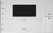
DC-p1
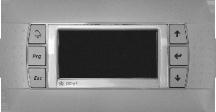
DC-p2 (DC-p2h)
S U M M A R Y O F D U P L E X C O N T R O L S Y S T E M S